

Raceways-Snake Tray Cable Tray-Megasnake-Megasnake Raceway System-Ladder Snake Tray-Ladder Rack Snake Tray-Snake tray 101 Deep Tray-Snake Tray Wall Snake-Snake Tray Fire Stop-Snake Tray Firestop-Snake Tray Fire Protection Systems-Under Floor Raceway-Overhead Raceway-Wall Raceway Solution-Power Raceway Solution-Snake Charmer-Snake Canyon-Mega Snake-Raceway Solutions-Megasnake Raceway Systems-Ladder Cable Tray-Solid Cable Tray-Trough Cable Tray-Channel Cable Tray-Wire Mesh Cable Tray-Single Rail Cable Tray-Multiconductor Cables-Multiconductor Cables in Cable Trays-Snake Loop-Snake Bus-Cable Tray-Cable Trays-Cable Tray Systems-Cable Tray Wiring-Cable Management-Cable Management Systems-Electriduct Supplier-Flextray-BasketTray-Snake Hook-Seismic Bracing-Snaketray Mounting Accessories-Cable Tray Distributor-Call Tollfree (866) 342-3721 or click the live support button below to talk to one of our representatives
Snake
Tray

American Data Supply now offers Snake Tray cable tray and raceway systems which is the world's only hand bendable cable management system that bends in any direction in seconds without cutting, clipping or sharp edges


American Data Supply now offers Snake Tray cable tray and raceway systems which is the world's only hand bendable cable management system that bends in any direction in seconds without cutting, clipping or sharp edges. American Data Supply also carries the entire line of Snake Tray-Raceway Systems- Cable Management- Underfloor Raceway- Overhead Raceways- Cable Tray-CableTray and Raceways. Generic wire basket cable tray systems will take up to 20 minutes to fabricate the same turn. Check out our underfloor, overhead and wall Snake Trays for your next project! You can click here for your own Snake Tray Raceway Design Wizard or get more information below.
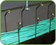
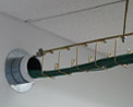
Snake Canyon® has revolutionized the way cable paths are created in a computer-raised floor environment. Snake Canyon integrates the structural elements of an access floor with a high capacity cable tray to create a cable path directly beneath the floor tile for easy access and installation.
![]()
Snake Bus Power Distribution System is the newest member in the Snake Tray family of products. Snake Bus brings you up to 15 kilowatts power where you want it - in seconds. Snake Bus’ streamlined design quickly installs to handle all your power needs in a computer access floor environment.
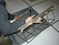
![]() Ladder
Rack Snake Tray
Ladder
Rack Snake Tray
![]() Snake
Tray 101 Deep Tray-
Snake Tray®
is pleased to announce the new larger size 18-inch wide and 4-inch deep cable
tray that creates 72 square inches of cable path to hold over 1000 Cat5e (.21
OD) cables
Snake
Tray 101 Deep Tray-
Snake Tray®
is pleased to announce the new larger size 18-inch wide and 4-inch deep cable
tray that creates 72 square inches of cable path to hold over 1000 Cat5e (.21
OD) cables

![]() Snake Tray Wall Snake®
Snake Tray Wall Snake®
CMS Snake Tray is pleased to present our
501 Series Snake Tray.
 Snake
Tray Fire Stop-Snake
Tray® is
pleased to announce the first in a series of new Snake Stop Fire Protection systems.
Snake
Tray Fire Stop-Snake
Tray® is
pleased to announce the first in a series of new Snake Stop Fire Protection systems.
 Wall Raceway Solution-Snake Wall
 Under
Floor Solution- Snake Canyon
Under
Floor Solution- Snake Canyon
 Power
Raceway Solution- Snake Bus
Power
Raceway Solution- Snake Bus
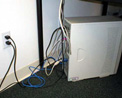 Snake
Charmer-Before
Snake
Charmer-Before 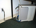
![]() Snake
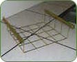
Charmer-After Snake Charmer™ Eliminates PC wire tangles and clutter
on workstations
Snake
Charmer-After Snake Charmer™ Eliminates PC wire tangles and clutter
on workstations
![]() Click-In
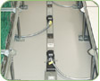
Snake Canyon® for Computer Access Floors
Click-In
Snake Canyon® for Computer Access Floors
Benefits:
Completely
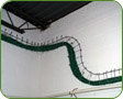
hand bendable, Snaketray’s unique design allows it to bend
in any direction
along any plane without tools or the need to cut wires.
Built-in mounting hardware reduces part numbers and cuts labor costs.
Snake Canyon compliments access floor installations with its “drop-in” installation method, locates cables directly below the floor tiles and provides complete separation from adjacent services.
Available
for use overhead, wall mount or under raised floors, CMS products
provide
unmatched site condition adaptability and superior affordability.
Snake
Tray bends (vertically & horizontally) by hand for an effortless transition
from floor to wall to ceiling and around obstacles without the need for accessories.
Open
architecture allows cables to enter and exit the tray at any point in any
direction. Simple clip-in cable “waterfalls” maintain proper bend radii
for cables.
What is Cable Tray?
1. What is a Cable Tray System?
2. What standards / guidelines are available for cable tray systems?
3. What types of Cable Tray are available?
4. How do I know what type of cable tray is right for my application?
5. What materials / finishes are available for the various cable tray systems?
6. Now that I know what types of cable trays are available, what configurations are available?
7. After selecting the type of cable tray and configuration required, what support methods are available?
8. Before selecting the type of cable tray, cable tray configuration(s), and support method desired, what additional information do I need to supply to the cable tray manufacturer for them to best understand and satisfy my needs?
Per
the National Electrical Code, a cable tray system is "a unit or assembly
of units or sections and associated fittings forming a rigid structural system
used to securely fasten or support cables and raceways."
What does this
mean?
* Cable trays support cable the way that roadway bridges support traffic.
* A bridge is a structure that provides safe passage for traffic across open spans.
* Cable tray is the bridge that allows for safe transport of wires across open
spans.
* Therefore, think of cable tray as the structural component of a building's
electrical system.
What standards / guidelines are available for cable tray systems?
1. The National Electrical Code publishes the standards for all types of electrical
applications. Articles 318, 250, and 800 cover various aspects of cable tray systems.
2. NEMA, (National Electrical Manufacturers Association), is an association comprised
of the major cable tray manufacturers in the industry. This committee has published
three documents to date: NEMA VE1, FG1 and VE2.
NEMA VE1 covers general cable tray definitions, manufacturing standards, performance standards, test standards, and application information. Free download of this document is available on the NEMA website.
NEMA FG1 addresses the standards for fiberglass cable tray systems. Free download of this document is available on the NEMA website.
NEMA VE2 is a cable tray installation guideline which covers receiving and unloading
material, storage of material, and general installation practices. Free download
of this document is available on the NEMA website.
3. CTI, (Cable Tray Institute),
is a trade association comprised of the major cable tray manufacturers in the
industry and was formed to provide specifiers, designers, and installers information
on the advantages of using cable tray systems over other types of products. (i.e.
conduit, ladder rack, etc.)
What types of Cable Tray are available?
1. Ladder Tray
2. Solid Bottom Tray
3. Trough Tray
4. Channel Tray
5. Wire Mesh Tray
6. Single Rail Tray
How do I know what type of cable tray is right for my application?
1. Ladder Cable Tray provides:
1. Solid side rail protection and system
strength with smooth radius fittings and a wide selection of materials and finishes.
2. maximum strength for long span applications
standard widths of 6,12,18,
24, 30, and 36 inches
3. standard depths of 3, 4, 5, and 6 inches
4. standard
lengths of 10, 12, 20 and 24 feet
5. rung spacing of 6, 9, 12, and 18 inches
Ladder cable tray is generally used in applications with intermediate to
long support spans, 12 feet to 30 feet.
2. Solid Bottom Cable Tray
provides:
1. Nonventilated continuous support for delicate cables with
added cable protection available in metallic and fiberglass.
2. Solid bottom
metallic with solid metal covers for nonplenum rated cable in environmental air
areas
3. standard widths of 6, 12, 18, 24, 30, and 36 inches
4. standard
depths of 3, 4, 5, and 6 inches
5. standard lengths of 10, 12, 20 and 24 feet
Solid Bottom cable tray is generally used for minimal heat generating electrical
or telecommunication applications with short to intermediate support spans of
5 feet to 12 feet.
3. Trough Cable Tray provides:
1. Moderate
ventilation with added cable support frequency and with the bottom configuration
providing cable support every 4 inches. Available in metal and nonmetallic materials.
2. standard widths of 6, 12, 18, 24, 30, 36 inches
3. standard depths of 3,
4, 5, and 6 inches
4. standard lengths of 10, 12, 20 and 24 feet
5. fixed
rung spacing of 4 inch on center
Trough cable tray is generally used for
moderate heat generating applications with short to intermediate support spans
of 5 feet to 12 feet.
4. Channel Cable Tray provides:
1. an
economical support for cable drops and branch cable runs from the backbone cable
tray system.
2. standard widths of 3, 4, and 6 inches in metal systems and
up to 8 inches in nonmetallic systems.
3. standard depths of 1¼-1¾
inches in metal systems and 1, 1 1/8, 1 5/" and 2 3/16 inches in nonmetallic
systems
4. standard length of 10, 12, 20 and 24 feet
Channel cable tray
is used for installations with limited numbers of tray cable when conduit is undesirable.
Support frequency with short to medium support spans of 5 to 10 feet.
5. Wire Mesh Cable Tray provides:
1. A job site, field adaptable support
system primarily for low voltage, telecommunication and fiber optic cables. These
systems are typically steel wire mesh, zinc plated.
2. standard widths of
2, 4, 6, 8, 12, 16, 18, 20, and 24 inches
3. standard depths of 1, 2, and
4 inches
4. standard length of about 10 feet (118")
Wire Mesh tray
is generally used for telecommunication and fiber optic applications and are installed
on short support spans, 4 to 8 feet.
6. Single Rail Cable Tray provides:
1. These aluminum systems are the fastest systems to install and provide the maximum
freedom fort cable to enter and exit the system.
2. Single hung or wall mounted
systems in single or multiple tiers.
3. Standard widths are 6, 9, 12, 18,
and 24 inches.
4. Standard depths are 3, 4, and 6 inches.
5. Standard
lengths are 10 and 12 feet.
Single Rail Cable Tray is generally used for
low voltage and power cables installations where maximum cable freedom, side fill,
and speed to install are factors.
What materials / finishes are available for the various cable tray systems?
1. Steel (Min. Yield = 33KSI) (35 KSI for Stainless)
1. Plain: hot rolled
pickled and oiled steel per ASTM A569 (Commercial Quality) or A570 (Structural
Quality)
2. Pre-Galvanized: mill galvanized steel per ASTM A653 CS (Commercial)
or SS (Structural) G90
3. Hot Dip Galvanized After Fabrication: plain steel
which is hot dipped after fabrication per ASTM A123.
4. Stainless Steel: type
304 or 316L fully annealed stainless steel
2. Aluminum (Min.Yield =
23 KSI)
1. 6063-T6 or 5052-H32 alloy per ASTM B209
3. Fiber Reinforced
Plastic (FRP)
1. Polyester and Vinyl Ester resin systems available
2.
meet ASTM E-84 smoke density rating; Polyester 680, Vinyl Ester 1025
3. Class
1 Flame Rating and self-extinguishing requirements of ASTM D-635.
Now that I know what types of cable trays are available, what configurations are available?
1. Straight sections are available to route cables in a horizontal or vertical
plane.
2. Fittings are available to route cables in various directions in
either the horizontal or vertical planes. Typical examples of fittings include
elbows, tees, crosses, and risers. Each of these fittings are available in various
radii and bend angles.
3. Covers are accessories and shouldn't be in here
unless splices etc. are included.
After selecting the type of cable tray and configuration required, what support methods are available?
1. Trapeze Support (Single or Multi-tier)
2. Hanger rod clamps, "J" hangers
3. Center Hung Support
4. Wall Support
5. Underfloor Support
6. Pipe stanchions or other structures
Each
of these support methods are preferable in different applications. For instance,
trapeze supports may be desired in an application where cables will be pulled
through the cable tray. Center hung supports, on the other hand, are generally
used when cables will be installed from the side of the cable tray. Center hung
supports are especially useful when future cable additions are desired. Wall supports
and underfloor supports are useful when ceiling structure is not available or
undesired. Outdoor installations are controlled by the structures available to
support the cable tray.
Before selecting the type of cable tray, cable tray
configuration(s), and support method desired, what additional information do I
need to supply to the cable tray manufacturer for them to best understand and
satisfy my needs?
Where? Job site and installation considerations
1. Outdoor
1. supports available affect the length and strength requirements
2. environmental loads, ice, wind, snow, and possibly seismic
3. corrosion
requirements affect the materials and finishes
4. classified hazardous locations
affect the cable types acceptable
2. Indoor
1. support locations available
affect the length and strength of the system
2. industrial installation may
require a 200 lb. Concentrated Load
3. commercial or institutional installation
may make system appearance, system weight, and space available important factors
4. environmental air handling area may affect cable types, cable tray material,
or cable tray type and need for covers
5. classified hazardous locations affect
the cable types acceptable
2. What?
1. Type and number of cables to support
1. NEC cable fill requirements
dictate size, width and depth, of system
2. cable support requirement may
control bottom type
3. largest bending radius of cable controls fitting radius
4. total of cable weight determines load to support
2. Future requirements
1. cable entry / exit freedom
2. design partially full or an expandable system
3. support type to allow for needs
Cable Tray Systems in Ducts, Plenums and Other Air Handling Space
The objective of this article to provide clear information as to the use of cable tray in those areas covered by Section 300-22 of the 1996 National Electrical Code.
Section 318-4 Uses Not Permitted states that "Cable tray systems shall not be used in environmental air spaces except as permitted in Section 300-22 to support wiring methods recognized for use in such spaces. The wiring methods allowed under Section 300-22 that utilize cable tray must follow the installation and safety requirements as covered in Section 318 - Cable Tray."
Many
of the misinterpretations about cable tray are due to the fact that those misinterpretations
are made with the thought that cable tray is a raceway. It is not a raceway and
it has never been a raceway in the National Electrical Code. Cable tray is a mechanical
support system just as strut is a mechanical support system. To install a metal
support system in an area rarely presents a fire safety problem. It is the cables
that are being supported by the cable trays that limit where a cable tray wiring
system may be installed. The only limitation on the cable tray is that it can't
be used in hoistways or where subject to severe physical damage. Any type of cable
tray may be installed in the areas covered by Sections 300-22(b), 300-22(c) and
300-22(d).
Installations for: Section 300-22(b). Ducts or Plenums for Environmental
Air.
The section states that Type MI (Mineral Insulated) cable or Type MC (Metal Clad) cable employing an impervious metal sheath without an overall non-metallic covering may be installed in Ducts or Plenums Used for Environmental Air. For such installations, both of these cable types may be supported by cable tray.
Section 318-3(a)(1) states that Type MI cable may be installed in cable tray for support. Section 330-12. Exception No. 2. states that "Type MI cable installed in cable trays shall comply with Section 318-8(b)." Ladder or ventilated trough cable tray is an ideal support system for Type MI cable. Where small numbers of Type MI cables are involved, ventilated channel cable tray is the ideal support system. Type MI cable is an excellent cable for critical circuits. It has a UL two hour fire resistive rating when properly installed. It is safest wiring method available.
Sections
318-3(a)(4) and 334-3(6) state that Type MC cable may be installed in cable tray
for support. Section 334-10(b) states that "Type MC cable installed in cable
tray shall comply with Article 318." Large amounts of the various types of
Type MC cable have been installed in cable tray. The performance record has been
excellent.
Installations for: Section 300-22(c) Other Spaces Used for Environmental
Air.
The Cable Tray Institute's Hot Line has received many requests for technical clarification assistance concerning Section 300-22(c). There are two problems with the material relating to cable tray in this section.
1. The wording in the second paragraph "or solid bottom metal cable trays with solid metal covers" implies that the types of insulated single conductors that are installed in raceways may also be installed in solid bottom cable trays with solid metal covers. Due to the present wording of Section 300-22(c), there have been some installation made that are not in compliance with Article 318. The cable tray was basically used as a wireway and in such cases the rules of Article 362 (Wireways) should apply. Depending on the specific installation, there may or may not be safety problems with such installations but Section 318-3(b) doesn't allow insulated single conductors to be installed in solid bottom cable trays.
Single conductor installations in cable tray have the following limitations:
1. The circuit conductors must be 1/0 AWG or larger [Section 318-3(b)(1)].(b)
They must be installed in ladder, ventilated trough or ventilated channel cable
tray [Section 318-3(b)].
2. Such installations are limited to qualifying industrial
establishments [Section 318-3(b)].
2. Some individuals have made erroneous interpretations of Section 300-22(c) concerning the types of cable tray that may be installed in "Other Space Used for Environmental Air." They assume that the wording of the second paragraph means that only solid bottom metal cable tray with solid metal covers may be installed in these installations. This is incorrect. Ladder, ventilated trough, ventilated channel or solid bottom cable tray may be installed to support the applicable types of cables specifically listed for the use.
Allowable Wiring Methods that may be supported by Cable Tray for Section 300-22(c) Installations.
Type
MI cables, Type MC cables without an overall non-metallic covering, Type AC cables
and other factory-assembled multiconductor control, power and signal cables that
are specifically listed for the use. Some of the multiconductor cables that are
listed as plenum cables with adequate fire-resistance and low smoke producing
characteristics are Type PLTC Cables (Article725), Fire Protective Signaling Cables
(Section 760), Optical Fiber Cables (Article 770) and Communication and Multipurpose
Cables (Article 800).
Installations for: Section 300-22(d). Data Processing
systems.
The appropriate types of cables that are used for branch circuit conductors and data handling or signal cables may be supported by cable tray under raised floors. The branch circuit cables in Section 645-5(d)(2) that may be supported in cable trays are Type MI cable, Type MC Cable and Type AC Cable. Section 645-5(d)(5) and Section 645-5(d)(5) Exception No. 3. list the various types of data and signal plenum cables with adequate fire-resistance and low smoke producing that may be installed in data processing facilities. These cables can be installed in any cable tray type. Due to the high wiring density, most raceway wiring methods are impractical for use in such installations while cable trays have the features which make them ideal for modern wiring methods.
Wiring changes can be made easily where the wiring method is cables in cable trays. Cable trays are the way to go for a state of the art wiring method that can easily accommodate changes at minimum cost in short time schedules.
Cable Tray Type Selection
What type of cable tray should be used for the main runs of a cable tray wiring system? The cable tray types to choose from are ladder, ventilated trough, or solid bottom. What are the reasons for selecting a specific type of cable tray?
The engineer or designer should select the type of cable tray that has the features which best serve the project's requirements.
For a few types of installations, the National Electrical Code (NEC) specifies the cable tray type to be used:
Single conductor cables and Type MV cables must be installed in ladder or ventilated trough cable trays. Single conductor cables and Type MV cables are not allowed to be installed in solid bottom cable trays [1993 NEC Section 318-3(b)]
In
Class II, Division 2 Hazardous (Classified) Locations (Dust), the types of cables
that are allowed to be installed in cable trays must be in ladder or ventilated
trough cable trays. Solid bottom cable trays are not allowed to be installed in
Class II, Division 2 locations [1993 NEC Section 02-(b)].
Ladder Cable Tray
Ladder cable tray is used for about 75 percent of the cable tray wiring system installations. It is the predominate cable tray type due to its many desirable features:
* A ladder cable tray without covers permits the maximum free flow of air across
the cables. This allows the heat produced in the cable's conductors to effectively
dissipate. Under such conditions, the conductor insulation in the cables of a
properly designed cable tray wiring system will not exceed its maximum operating
temperature. The cables will not prematurely age due to excessive operating temperatures.
* The rungs of the ladder cable trays provide convenient anchors for tying down
the cables in the non-horizontal cable tray runs or where the positions of the
cables must be maintained in the horizontal cable tray runs. This capability is
a must for single conductor cable installations. Under fault conditions (short
circuit), the magnetic forces produced by the fault current will force the single
conductor cables from the cable tray if they are not securely anchored to the
cable tray.
* Cables may exit or enter the ladder cable trays through the
top or the bottom of the cable tray. Where the cables enter or exit conduit, the
conduit to cable tray clamps may be installed upright or inverted to terminate
conduits on the top or bottom of the cable tray side rail.
* Moisture can't
accumulate in ladder cable trays.
* If cable trays are being installed where
working space is a problem, hand access through the cable tray bottom may help
to facilitate the installation of small diameter cables: control instrumentation,
signal, etc.
* The most common rung spacings for ladder cable tray is 9 inches.
This spacing may be used to support all sizes of cables This spacing is desirable
for the small diameter Type PLTC and TC cables as the support distance is such
that there is no visible drooping of the small cables between rungs. 12 or 18
inch rung spacing provides adequate cable support but the slight amount of small
diameter cable drooping between rungs may be aesthetically objectionable for some
installations. The maximum allowable distance between supports for 1/0 through
4/0 AWG single conductor cables is 9 inches [1993 NEC Section 318-3(b) (1)].
Ventilated Trough Cable Tray
The
only reason to select a ventilated trough cable tray over a ladder type cable
tray is aesthetics. No drooping of small cables is visible. The ventilated trough
cable tray does provide more support to the cables than does the ladder cable
tray but this additional support is not significant. It doesn't have any impact
on the cables service record or life.
Solid Bottom Cable Tray
The main reason for selecting solid bottom cable tray (with covers) is the concern of EMI/ RFI shielding protection for very sensitive circuits. A solid bottom steel cable tray with steel covers provides a good degree of shielding if there are no breaks or holes in the completed installation.
The solid bottom cable tray system has a disadvantage in that moisture can build up in the cable trays. This can be controlled by drilling 1/4 inch drain holes in the bottom of the cable tray at three foot intervals (at the middle and very near the sides) if the cable tray is not being used for EMI/RFI shielding.
Some engineers and designers specify solid bottom cable trays (often with covers) in the belief that all electrical circuits have to be totally enclosed by metal. The cable trays are just supporting cables that are designed for such installations. Cable failures in cable tray runs rarely happen. Cable failures due to cable support problems in cable trays are nonexistent.
Cable Tray Wiring Systems Have Many Cost Advantages
Cost is usually a major consideration in the selection of a wiring system. This article provides information as to where cable tray wiring system cost savings will occur; however, it is not the intent of this article to state that the selection of a wiring system should be based only on cost.
Early in the life of a project, the costs and the features of the applicable wiring methods should be evaluated to provide decision information for the selection of the best possible wiring method or methods for the project. The evaluations should include items that relate to cost, dependability, future changes, maintenance, safety, and space savings. Usually the evaluation will determine if a cable tray wiring system or a conduit wiring system is to be selected as the projects major wiring system. Both large scale and small cable tray wiring systems have been in use for the last 45 years in North America and longer in other parts of the world. Forty-five years of operating experience has proven that cable tray wiring systems are superior to conduit system wiring systems for power, control signal and instrumentation circuits.
The following functions must be properly executed to obtain a quality wiring system installation:
1. Select the most desirable wiring method.
2. Properly design the wiring
systems.
3. Specify quality materials.
4. Plan and execute the installation's
sequence of activities and the techniques to be used.
5. Control of the quality
of the installation.
Depending on the type of circuits and the wiring density, an installed cable tray wiring system may result in a total cost reduction (material + labor) of up to 60 percent compared to the cost of an equivalent conduit wiring system. There is also the potential for cost savings to occur in the design, material procurement, installation and maintenance areas when the wiring system is a cable tray wiring system.
Potential Design Cost Savings:
1.Very few projects are completely defined at the start of design. As a project progresses through the design phase, the operating logic and safety requirements are developed and refined. The changes and additions required to meet the projects needs occur all through the design cycle and at times even into the initial construction phase. For projects that are not 100 percent defined before the start of design, the cost of and time used to cope with changes during the engineering and drafting design phases will be substantially less for a cable tray wiring system than for an equivalent conduit system.
It only takes a few minutes of design time to change the width of a cable tray
to gain significant additional cable fill capacity. For an additional cost of
less than 10 percent of the basic cable tray cost, 6 inches of additional cable
tray width can be obtained. This extra 6 inches will accommodate large numbers
of small diameter analog and/or digital signal cables. Where banks of conduits
are involved, any change in wiring capacity requirements during the late stages
of engineering and drafting design are very costly and time consuming. Significant
conduit system additions or revisions are usually required to provide exit and/or
entry points in the conduit runs for the circuit additions made late in the design
phase. Cable tray's unique feature that allows a cable to enter or exit a cable
tray anywhere along the cable tray's route provides for the easy accommodation
of cable additions. No raceway wiring system has this unique feature.
2. Using
cable tray wiring systems simplifies the overall wiring system design process
as fewer details are required for properly designed cable tray runs than for properly
designed conduit banks. Conduit system design can be very complex due to the need
for pull boxes, splice boxes and the involved conduit bank supports.
3. The
fact that a cable tray system isn't required to be mechanically continuous eliminates
the need for many complex installation details for conductor/cable entries into
equipment and in dealing with cable tray run interferences.
4. The installation
space requirement is smaller for a cable tray than an equivalent capacity conduit
system. For cable tray systems, there is less apt to be space conflicts with other
engineering disciplines on a project than for a conduit system. Coordination design
time is saved by dedicated fixed dimensioned installation zones for the cable
tray system. The cable tray installation zone's size will not grow as changes
are made as it does for conduit banks in large projects.
5. Wire management
systems for cable tray wiring systems consume less design time than is required
for a conduit system. A spread sheet based wire management program may be used
to control the cable tray fill. While such a system may also be used for controlling
conduit fill, large numbers of individual conduits will require fill monitoring
while only a few cable tray runs require fill monitoring for an equivalent capacity
wiring system.
Potential Material Procurement Costs Savings:
1. There are fewer different components in a cable tray wiring system than in
a conduit wiring system. Fewer different components means savings due to fewer
components to specify, order, receive, store and distribute.
2. Excluding
conductors, the cost of the cable trays, supports and miscellaneous items may
provide a material savings of up to 80 percent as compared to the cost of conduits,
supports, junction boxes, pull boxes and miscellaneous materials. The NEC fill
capacity for an 18-inch wide ladder or ventilated trough cable tray is 21 square
inches. It takes seven - 3 inch conduits to match that fill capacity.
3. For
feeders or branch circuits, where the installations involve parallel phase conductors,
there is a copper cost savings for cable tray wiring systems. The derating factors
don't apply to three conductor or single conductor cables in cable tray as they
do for conduits. For the same circuit capacity of paralleled phase conductors,
the cable tray installation uses fewer pounds of copper than the conduit installation.
Where phase conductors are not paralleled, the cost of the 600 volt multiconductor
cables used in cable trays is greater than the cost of the single conductor cables
used in conduit. This cost difference depends on the insulation systems, jacket
materials and cable construction.
Potential Installation Cost Savings:
1. The installation of a cable tray wiring system requires fewer man-hours than
an equivalent conduit wiring system. This is where the major cost savings are
obtained for the cable tray wiring system. Smaller sized electrician crews may
be used to install a cable tray wiring system as compared to an equivalent conduit
wiring system. This allows for manpower leveling, the peak and the average crew
size would be almost the same number. The electrician experience level required
for cable tray can be lower than that for a conduit wiring system as fewer electrician
with conduit bending skills are required.
2. Cable trays can be installed
faster than conduit banks. Since the work is completed in a shorter time period
there is less work space conflict with the other construction disciplines. This
is especially true if the installations are elevated and significant amounts of
piping are being installed on a project.
3. Many more individual components
are required in a conduit system than in a cable tray system. This results in
the handling and the installing of large amounts of individual conduit items vs.
small amounts of individual cable tray items. At elevated installation levels,
many additional man-hours will be required to transport the components needed
for the conduit system up to the installation level.
4. Conduit systems contain
materials and installation practices that are more complex and costly to install
than those used in cable tray systems. This is the reason that cable tray installation
labor costs are significantly below conduit system installation labor costs. Conduit
systems require pull or splice boxes where there is the equivalent of more than
360 degrees of bends in a run. Cable tray systems don't require pull or splice
boxes. Conduit systems normally require more supports and the supports are more
complex. When penetrating walls, conduits banks require larger holes and more
repair work than is required for cable trays.
Concentric conduit bends for direction changes in conduit banks are very labor
intensive and costly. However if they are not used, the installation will not
be very attractive. The time required to make a concentric bend is increased by
a factor of three to six over that of a single shot conduit bend. This labor intensive
practice is eliminated when cable tray wiring system are used.
5. Conductor
pulling is more complicated and labor intensive for conduit wiring systems than
for cable tray wiring systems. For conduit systems, it is necessary to pull from
equipment enclosure to equipment enclosure. The conduit system is required to
be mechanically continuous from equipment enclosure to equipment enclosure. Tray
cables being installed in cable trays don't have to be pulled through or into
the equipment enclosures. Tray cable may be pulled from near the initial enclosure
along cable tray route to near the termination enclosure, then the tray cable
is inserted into the equipment enclosures for termination. Making the conduit
system wire pulls through the enclosures increased the possibility of conductor
insulation damage.
Potential Maintenance Cost Savings:
1. An article in the October 1991 EC&M magazine, "Cable Pulling for Conduit Wiring Systems," stated that 92 percent of the insulated conductors that fail do so due to the fact that they were damaged during installation. The failures of the insulated conductors may create unnecessary safety conditions and significant cost problems. Why not select a wiring method where during the past 45 years its conductor failures due to installation damage have been almost non-existent? Cable tray with quality cables is that wiring method.
Conductor insulation failures in cable tray wiring systems are rare. The reason
for this that the tray cables are rarely damaged during the installation. Many
of the conduit conductors that fail do so due to the fact that they have been
damaged when they were pulled into the conduits. Excessive forces imposed on the
conductor's insulation system during the conductor installation process can be
very destructive. For some critical combinations of conductors and sizes of conduit,
jamming of the conductors in the conduit can occur during the conductor installation.
This may result in conductor insulation damage. Critical jam ratio (J.R. = Conduit
ID/Conductor OD) values range from 2.8 to 3.2. The 1996 NEC Chapter 9 Table 1.
Fine Print Note is an alert for this serious problem.
2. If circuit additions
are made in the future, the fact that the cables can enter or exit the cable tray
anywhere along its route allows for the cable additions at the lowest possible
future cost. This is a feature that is unique to cable tray. Future cable fill
space capacity to accommodate cable additions to a cable tray can be provided
at a very low cost.
3. The cable tray wiring systems reduce the potential
for moisture related equipment failures. Tray cables don't provide the internal
moisture paths that conduits do. This lowers future maintenance costs. Moisture
is a major cause of electrical equipment and material failures. The day to night
temperature cycling results in moisture laden air being drawn into the conduits
and the moisture in the air condensing. The condensed moisture accumulates in
conduits systems. The conduits pipe the accumulated moisture into the electrical
equipment enclosures. Over time, this moisture may accelerate the corrosion of
some of the equipment's metallic components and deteriorate the equipment's insulation
systems to failure. Conduit seals are not effective in blocking the movement of
moisture. Conduit systems have to be specifically designed to reduce moisture
problems and this is rarely done.
4. A properly designed and installed wiring
system will not be a fire ignition source. It is possible that the wiring system
may be exposed to an external fire. For a localized fire, the damage to a cable
tray wiring system will be less to a cable tray system than to the conduit system.
This has been the case in some industrial facility fires. The damage to PVC jacketed
tray cables and the cable tray is most often limited to the area of flame contact
area plus a few feet on either side of the flame contact area. When such a fire
envelopes a steel conduit bank, the steel conduit is a heat sink and the insulation
of the conduit's conductors will be damaged for a considerable distance. Thermoplastic
insulation may fuse to the steel conduit and the conduit will need to be replaced
for many feet. This occurred in an Ohio chemical plant. The rigid conduit had
to be replaced for 90 feet. Under such conditions, the repair cost for fire damage
would normally be greater for a conduit wiring system than for a cable tray wiring
system. In the Ohio chemical plant fire, large banks of conduit and multiple runs
of cable tray were involved. The cable tray wiring systems were repaired in two
round-the-clock days, and the conduit wiring systems were repaired in six round-the-clock
days. The conduit system repair required more than three times the man-hours that
was used for the cable tray system.
In the July 1995 EC&M magazine, "Protecting Life Safety Circuits In High Rise Buildings" the section titled "Protecting signal and communication wiring" states the following: "Results of Steiner Tunnel testing performed by various cable manufacturers actually indicates that conduits tend to act as heat sinks, thereby decreasing the time required to damage insulation to cause conductor failures." This is a big negative for conduit systems.
Cable tray wiring systems have significant cost savings advantages over conduit wiring systems. They also have convenience, dependability and safety advantages over conduit wiring systems.
Cable
Tray Grounding: Power, Instrumentation, and Telecommunications
Richard J. Buschart,
Technical Director-Cable Tray Institute
Grounding has always been a controversial topic. But, with the growth of digital high frequency systems the issues are more complex. Grounding means connected to earth or a conducting body that acts in place of earth. Some international standards refer to grounding as earthing. Bonding is the interconnection of metal parts to establish electrical continuity. These definitions are NEC terminology and apply to power system grounding.
The purpose of grounding is:
* Fire Protection
* Electrical Shock Protection
* Electrical system ground
fault protection
* Lighting protection-building and electrical system
* Electrical Noise and EMI protection
* Voltage Stabilization
Power
System Grounding
Power circuit grounding of cable trays is explained in CTI
Technical Bulletins, Titles No. 8, 11, and 12, and the National Electrical Code
Sections 318-3-© and 318-7. It is also covered in NEMA Standard VE-2.
The purpose of power grounding (Article 250) is to minimize the damage from wiring or equipment ground fault. Cable tray systems are in the path of ground fault currents. Cable tray systems are bonded together through their bolting, connectors splice plates, clamps, and bonding jumpers where there are gaps in the cable tray system. Cable tray systems are not required to be mechanically continuous, but shall be electrically continuous.
Cable trays are also bonded to conduit, cable channel or other wiring drops. They must also be bonded back to the power source. All bonding jumpers must be sized (as a minimum) to meet the requirements of equipment grounding conductors. Both side rails of the tray must be bonded together to the next section. Cable trays can be used as the only equipment grounding conductor (EGC), but they must meet certain criteria (only in qualifying facilities, minimum cross-sectional areas, U.L. classified as to suitability, etc., see NEC 318-7).
There are other alternatives-use EGC’s in the cable (U.L. listed cable can be supplied with ECG’s in certain conductor sizes) or a separate EGC in the cable tray that bonds the cable tray sections together and can also be used to tap EGC’s to individual drop-outs from the CT. These two alternatives can be used for non-metallic cable trays. Cables with equipment ground conductors within the cable are an accepted practice in industry. They provide a two-point connection from the power source to the load, however, any conduit, cable tray, or raceway must still be bonded back to the power source.
Some companies do not accept conduit as an EGC.
The EGC system is a critical safety system. Therefore, it is prudent to treat the cable tray system as an equipment grounding conductor in parallel with the ground conductors in the cables or an individual ground conductor.
Cable
Tray Grounding-Signal and Communication Circuits
Where cable tray systems contain
only signal and communication circuits that operate at low energy levels, power
grounding per NEC Section 318-7 is not appropriate, but cable tray grounding for
lightning protection, noise, and electromagnetic interference is necessary. For
telecommunications circuits TIA/EIA standard 607, Commercial Building Grounding
and Bonding Requirements for Telecommunications, provides grounding for these
systems. Voltage disturbances, lightning induced voltages, and radiated EMI are
the concern. Lightning protection is a concern if cable trays are located on the
top of buildings, in an outdoor exposed area, or in the path of lightning currents.
An overhead cable system can provide protection. NFPA780, Standard for the Installation
of Lightning Protection Systems 1997 Edition, provides the criteria for building
lightning protection.
Cable tray designs are also available that are EMI/RFI shielded. The tray is totally enclosed and the gaskets and covers are constructed and tested to meet EMI standards for the protection of the sensitive circuits in the cable tray against external electric and magnetic fields. Solid bottom cable trays also provide some degree shielding as do cable tray covers. Steel provides effective shielding at frequencies up to approximately 100 kilohertz however at higher frequencies, in the megahertz range, aluminum or copper shielding is more effective.
Cross
Talk
Cable tray systems that contain signal and communication circuits should
be grounded and, in some situations, shielded from external electrical and magnetic
disturbances. In addition to these concepts, the CTI has received a number of
questions concerning the coupling of electrical noise from power wiring into sensitive
circuits because the wiring is within the same cable tray or close to the cable
tray. The key question is how far apart does the power and signal cables have
to be. The most desirable design is to separate power and signal cables in separate
cable trays, or to separate wiring systems by a barrier.
The sensitivity of signal systems depends on a number of complex factors. Including electronic circuitry involved, isolation or coupling to ground, filtering, the signal type and logic, type of signal cable (untwisted pair, twisted pair, shielded twisted pair, coaxial cable double-shielded coaxial cable) and characteristic impedance of the circuit and cable. Some systems are quite tolerant to external noise. For instance, 4 to 20MA instrument signal systems and telecommunication circuits do quite well with respect to noise.
Some companies and organizations have published their own recommended practices and they should be followed. The national standard that includes separation distances is the Institute of Electrical Electronic Engineers (IEEE) Standard 518, IEEE Guide for the Installation of Electronic Equipment to Minimize Electrical Noise Inputs to External Sources. The cable spacing criteria found in this standard is large, based on industry experience. Many systems work quite well with lesser distances. Much depends on the particular installation. Typical spacing of cables in trays used in various industry standards varies from two inches to four feet. In some situations, two inches is probably adequate.
AC
Drives
There have been a number of noise problems (and other problems) with
the application of the newer IGBT AC Pulse Width Modulated Adjustable Speed Motor
Drives. The new IGBT Drives produce fact rise time pulses that produce high voltage,
high frequency pulses in the power wiring from the Inverter electronics to the
motor. (The IGBT is a new type of power semiconductor.) This power wiring is essentially
a radiator of high frequency power.
The noise frequency can be as high as 30MHZ. A number of IEEE papers have been presented on this topic. In particular, they provide detailed studies analysis and noise measurements using different types of motor power cable types. The conclusion is that one can manage this concern by proper grounding and power cable selection. At these frequencies, based on tests, the power cable should be shielded with a metal armor or foil either copper or aluminum. These studies and technical papers indicate that:
1. Shielded cable-either type TC or MC should be used
2. Nonferrous metal,
such as aluminum, becomes the metal of choice at high frequencies for the cable
shield
3. Additional high frequency bonding is required
Conclusion
Cable
tray systems have been used extensively to support sensitive electronic circuitry.
For many circuits shielding and separation requirements are minimal. Proper attention
to the following can manage noise and EMI concerns:
* Signal cable
* Grounding of signal circuits and cable shields
* Cable
selection
* Cable tray grounding
Tie Down Practices for Multiconductor Cables in Cable Trays
The value of any practice that increases a system's cost and complexity should be justified. Is the practice serving mandatory functions or is the practice encompassing both mandatory and useless functions? The objective should be to eliminate the useless functions and to serve the mandatory functions in the best possible manner at the lowest- possible cost. This is the approach that should be taken when developing standard practices for tying down multiconductor cables in cable trays. In many cable tray wiring systems, the tying down of multiconductor cables is a useless function.
There
are three items which require decisions concerning the tying down of multiconductor
cables in cable tray wiring systems. Item #1 is to define under what conditions
the multiconductor cables in cable trays are to be tied down. Item #2 is to define
the frequency at which the multiconductor cables are to be tied down. Item #3
is to select the ties that have the proper characteristics for the specific installations.
In the following material, where the word cable is used it means multiconductor
cable.
Item #1- Conditions Requiring Cable Tie Down:
The reasons for tying down cables are to keep them in the cable trays, to maintain the proper spacing between cables, or to confine the cables to specific locations in the cable trays. National Electrical Code Section 318-8(b) states that in other than horizontal cable tray runs, the cables shall be fastened securely to transverse members of the cable trays. In horizontal cable tray runs, cables are not required to be tied down. The cable's weight will keep them in the cable trays. In non-horizontal cable tray runs, the cables must be tied down. For a vertical cable tray installation, the cables may hang away from the cable tray if they are not tied down. The more flexible small diameter cables will hang further away from the cable trays than the large diameter cables if they are not tied down. The smaller diameter cables will need to be tied to the cable tray more frequently than the stiff large diameter cables.
Cable installations as per 1993 EC Sections 31811(a). Exception #2 and 318-13(a). Exception #2 require that a space equal to the diameter of the larger cable be maintained between adjacent cables for heat dissipation reasons. The way to make sure that this spacing is maintained is to tie down the cables.
Type MC or TC cable installations as per 1993 NEC Section 502-4(b) require that a space equal to the diameter of the larger cable be maintained between adjacent cables to reduce the impact of dust build up and heat dissipation problems in Class II, Division 2 Combustible Dust Areas. The way to make sure that this spacing is maintained is to tie down the cables.
There are installations where the owner may want the cables tied down to guarantee the separation of low energy signal cables and power cables. This condition may also be obtained by installing a permanent barrier in the cable tray.
For installations where a single large cable or several cables are installed in ventilated channel cable trays, it is at times desirable to tie the cables to the horizontal as well as to the non-horizontal ventilated channel cable trays. Then if an abnormal condition occurs, the cables would not be knocked out of the ventilated channel cable trays which are only 1 1/2 inches high.
Where Type MI cables are installed that are to have two hour fire resistant ratings, the MI cables must be securely supported every three feet. A desirable installation would be to install the MI cable in steel cable trays and to use stainless steel ties to secure the MI cable to the cable tray every three feet.
Where
cables drop from the cable trays to equipment enclosures, it may be desirable
to anchor the cables to the last one, two or three rungs before the drop depending
on the size of the cables. This easily provides distributed secured support for
the cables when the length of cable between the cable tray and the equipment enclosure
is six feet or longer.
Item #2 - Comments on Cable Tie Down Frequencies:
The NEC doesn't specify any distances between ties for cables in cable tray wiring systems. This is a decision that must be made by those designing and installing the cable tray wiring systems. It is desirable to develop some standards for this activity.
A conservative recommendation for non-horizontal cable trays is that the small diameter cables (diameters less than 1 inch) be tied down at approximately 3 foot intervals and that cables 1 inch and larger be tied down at approximately 6 foot intervals.
The vertical cable wiring system installations that contain horizontal bends require the cables to be tied down at every or every other rung in the bend and to the first rung before entering the bend and the first rung after exiting the bend.
In
horizontal cable trays where cable spacing is to be maintained, the cables should
be tied down at approximately 10 foot intervals. For horizontal ventilated channel
cable trays, there are installations containing a single large cable or several
cables where it is desirable to tie down the cables at approximately 10 foot intervals.
Item
#3 - Comments on the Types of Cable Ties:
Designers should select cable ties that have the proper characteristics for the specific installations. The initial installation of the wrong cable ties may require maintenance expenditures to replace the cable ties. Plastic ties that are not ultraviolet resistant will fail in one to two years if they are installed where they are exposed to the rays of the sun. Where both indoor and outdoor cables are to be tied down on the same project, it is best to have only ultraviolet resistant ties on the project and use them on both the indoor and the outdoor cables. This way it will not be possible to have the incorrect type of ties for the outdoor cables.
When selecting cable ties the following must be considered: moisture resistance, ultraviolet resistance, extremely high ambient temperatures, extremely low ambient temperatures, chemical resistance, flammability (UL 94 V-O flammability rating), low smoke characteristics, tensile strength, appropriate lengths (the surplus lengths of the cable ties are cut off so it is possible to use one tie length as standard where many different lengths are required). There are quality plastic ties available that if properly applied have a life span of up to 20 years. There are non-magnetic stainless steel ties as well as the plastic ties. The stainless steel ties are capable of satisfactorily satisfying a wide range of requirements.
Home | Cables | Switches | Contact Us | Our Team | Locations
 |
 |
|
 |
 |
|
 |
 |
|
 |
||
 |
 |
|